

Jet 15 Milling Machine Manual
- Contents Table of Contents
- Bookmarks
Quick Links
JMD-15/18/18PFN Mill/Drill Machine
JET
WMH Tool Group
www.wmhtoolgroup.com
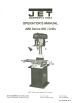
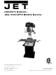
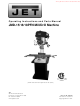
OWNER'S MANUAL
(JMD-18 shown with optional CS-18 stand)
P.O. BOX 1349
Auburn, WA 98071-1349
e-mail jet@wmhtoolgroup.com
Phone: 253-351-6000
Fax: 1-800-274-6840
M-350020 05/02

Also See for Jet JMD-15
Related Manuals for Jet JMD-15
Summary of Contents for Jet JMD-15
- Page 1 OWNER'S MANUAL JMD-15/18/18PFN Mill/Drill Machine (JMD-18 shown with optional CS-18 stand) P.O. BOX 1349 Phone: 253-351-6000 WMH Tool Group Auburn, WA 98071-1349 Fax: 1-800-274-6840 www.wmhtoolgroup.com e-mail jet@wmhtoolgroup.com M-350020 05/02...
-
Page 2: Warranty
We will return repaired product or replacement at JET'S expense, but if it is determined there is no defect, or that the defect resulted from causes not within the scope of JET'S warranty, then the user must bear the cost of storing and returning the product. -
Page 3: Warning
13. Keep children and visitors away. WARNING visitors should be kept a safe distance from Read and understand the entire contents of the work area. this manual before attempting set-up or operation of this mill/drill. 14. Make the workshop child proof. padlocks, master switches, and remove 1. -
Page 4: Table Of Contents
Number of Power Downfeeds (JMD-18PFN only) ..................3 Range Of Power Downfeeds (JMD-18PFN only)............0.004", 0.007", 0.001" Number of Spindle Speeds: All Models ............................12 Range of Spindle Speeds: JMD-15 ........................110 – 2,580 RPM JMD-18/18PFN......................150 – 3,000 RPM Maximum Table Travel: JMD-15 ............................14" JMD-18/18PFN.........................20-1/2"... -
Page 5: Table Of Contents
JMD-18PFN ..................42-1/2"L x 39-3/4"W x 51-1/2"H Base Dimensions: JMD-15 ........................12-1/2" x 19-3/4" JMD-18/18PFN......................15-3/4" x 23-3/4" Motor (UL Listed): JMD-15 ................... 1 HP, 1Ph, 115V/230V Prewired 115V JMD-18/18PFN....................2 HP, 1Ph, 230V only Net Weight (approx.): JMD-15 ..........................440 Lbs. JMD-18 ..........................660 Lbs. -
Page 6: Contents Of The Shipping Container
1. 1/2" Drill Chuck w/ Chuck Key 1. Adjustable Carbide Facemill 1. Facemill Arbor 2. Bolts, Nuts, and Washers to Attach Vise to Table 1. 2-1/2" Angle Vise (JMD-15) 1. 3-1/2" Angle Vise (JMD-18/18PFN) 3. Handle Rods 3. Rubber Knobs 1. 3/8"x1" Hex Socket Cap Screw 1. -
Page 7: Assembly
Assembly bolts. Check for level again. Adjust as necessary until the mill/drill is level after the 1. Screw rubber handles (A, Fig. 1) onto fastening hardware has been tightened. handle shaft (B, Fig. 1). Screw handle shaft into downfeed hub (C, Fig. 1) and tighten. Flat spot shaft... -
Page 8: Lubrication
Also, press the "Off" button on the front of the machine before connecting to the power source. The JMD-15 is rated at 115/230V and comes from the factory prewired at 115V. This mill/drill comes with a plug designed for use on a circuit with an outlet that looks like (A, Fig. -
Page 9: Controls
Turn clockwise to lock. Depth Stop: JMD-15: (K, Fig. 8) located on the left side. Set nuts for desired depth stop. JMD-18: (F, Fig. 7) located in the front. Push in the button on the front of the quick adjust stop and move to desired position. -
Page 10: Changing Spindle Speeds
Motor Mount Lock Lever: (A, Fig. 9) Located on the right side of the head casting. Locks and unlocks the motor mounting plate enabling the user to tension v-belts. Head Pivot Lock: (B, Fig. 9) Located on the right rear of the head casting. Loosen two hex nuts to rotate the head 360°. -
Page 11: Arbor Replacement
4. Arrange the v-belts (A, Fig. 12) on the Note: For best results, all milling operations pulleys (B, Fig. 12) for the desired speed should be done with the quill/spindle as close to according to the speed chart (H, Fig. 11) on the head assembly as possible. -
Page 12: Gib Adjustment
Gib Adjustment 2. Loosen knob (I, Fig. 15) just enough to rotate spring cap past the notch (J, Fig. 15). After a period of time, movement of the table 3. Rotate the spring cap clockwise to decrease over the ways will cause normal wear. spring tension. -
Page 13: Jmd-15 Parts Lists And Breakdowns
JMD-15 Head Assembly... - Page 14 Parts List for the JMD-15 Mill/Drill Head Assembly Index Part Description Size Qty. 1..JMD15-001 ....Drawbar....................1 2..JMD15-002A ....Spindle Lock Nut .................. 1 3..JMD15-003 ....Spindle Pulley..................1 5..JMD15-005 ....Outer Bearing Plate ................1 6..JMD15-006A ....
- Page 15 Index Part Description Size Qty. 67 ..JMD15-067 ....Motor..............1HP, 1Ph....1 ....JMD15-067A ....Capacitor (not shown)........125uF, 250VAC ..1 69 ..JMD15-069P ....Belt Cover .................... 1 69-1..JMD15-069P1 ....Upper Belt Cover Cap................1 69-2..JMD15-069P2 ....Upper Belt Cover Plate................. 1 70 ..JMD15-070 ....
- Page 16 208 ..TS-0561031 ....Hex Nut ............. 3/8"......1 ....JMD15-SC ....Speed Chart Label (not shown)............. 1 ....JMD15-JL ....Jet Label (not shown)................1 ....JMD15-ID..... I.D. Label (not shown)..................JMD15-AP ....Accessory Package (not shown) * ............1 ....JMD18-302 ....
- Page 17 JMD-15 Table, Base, and Column Assembly...
- Page 18 Parts List for JMD-15 Table, Base, and Column Assembly Index Part Description Size Qty. 1..JMD18-201 ....Table Hand Wheel................3 1-1..JMD18-201-1 ....Bolt....................... 3 1-2..JMD18-201-2 ....Handle....................3 1-3..JMD18-201-3 ....Nut ....................... 3 2..JMD18-202 ....Dial Clutch.................... 2 2-1..JMD18-202-1 ....
-
Page 19: Jmd-18 Parts Lists And Breakdowns
JMD-18/18PFN Head Assembly... - Page 20 Parts List for the JMD-18 Mill/Drill Head Assembly Index Part Description Size Qty. 1..JMD18N-001....Head Body.................... 1 2..JMD18-001 ....Draw Bar ............R8 ......1 3..JMD18-002A ....Spindle Lock Nut .................. 1 4..JMD18-003A ....Spindle Pulley..................1 5..JMD18-005 ....
- Page 21 Index Part Description Size Qty. 32 ..JMD18-047 ....Round Head Screw..........3/16"x3/8" ....2 33 ..JMD18N-033....Micro Adjusting Indicator ..............1 33-1..TS-0267021 ....Set Screw............1/4"x1/4" ..... 1 35 ..JMD18N-035A....Feed Handle Wheel Assembly.............. 1 35-1..JMD18N-035-1..... Set Screw............M8x10 ......1 37 ..JMD18-105 ....
- Page 22 115 ..JMD18N-115....Power Cable ............230V......1 116 ..JMD18N-116....Lamp Assembly ..........115V......1 117 ..JMD18N-117....Motor Cable..................1 ....JMD15-JL ....Jet Label (not shown)................1 ....JMD18-ID..... I.D. Label (not shown)..................JMD18-AP ....Accessory Package (not shown) * ............1 ....JMD18-302 ....
- Page 23 JMD-18 Table, Base, and Column Assembly...
- Page 24 Parts List for the JMD-18 Mill/Drill Table, Base, and Column Assembly Index Part Description Size Qty. 601 ..JMD18-228 ....Table ..............31L ......1 602 ..JMD18-229 ....Fixed Block................... 2 603 ..JMD18-230 ....Movable Ring ..................2 604 ..
- Page 25 Index Part Description Size Qty. 635-6 ..JMD18-366 ....Pin..............5x38 ......1 636 ..JMD18N-636..... Column Base..................1 637 ..JMD18N-637..... Rack..............600.5L ......1 638 ..JMD18-211 ....Column Cap ..................1 638-1 ..TS-0270021 ....Set Screw............5/16"x5/16" ....1 640 ..
- Page 26 JMD-18PFN Power Feed Assembly...
- Page 27 Parts List for the JMD-18PFN Power Feed Assembly Index Part Description Size Qty. 248 ..290111...... Main Pulley................... 1 249 ..JMD18PFN-249 ..Set Screw............1/4"x3/8" ..... 2 ....291022AS ....Complete Gear Box Assembly.............. 1 401-1 ..291022A ....Gear Box ..................... 1 401-2 ..
- Page 28 Index Part Description Size Qty. 403-1 ..2450048....Worm Gear Cover ................1 403-2 ..JMD18PFN-346 ..Flat Cross Head Screw ........M4x4 ......3 403-3 ..JMD18PFN-320 ..C-Ring ............... S25......1 403-4 ..2450024....Clutch Gear Case ................. 1 403-5 ..
-
Page 29: Jmd-15 Wiring Diagram
Wiring Diagram JMD-15... -
Page 30: Jmd-18 Wiring Diagram
Wiring Diagram JMD-18 230V Only...
Source: https://www.manualslib.com/manual/622070/Jet-Jmd-15.html
0 Response to "Jet 15 Milling Machine Manual"
Post a Comment